Research question and scope
While rowing a fixed-seat, moving-row-box boat on Lake Union in Seattle in summer 2026, Jerry Decime found that attempts to apply his accustomed power would push him off the seat. This evaluation was undertaken to test whether seat contact mechanics could explain and corroborate that observation. The experience is the study’s motivation, not an instrumented measurement of power loss. The modeled question is: under specified loads and support assumptions, does the required horizontal seat force exceed the available grip? The outcomes are contact-force demand, friction capacity, and relative sliding.
In the moving-seat configuration, the seat travels while the foot support and oarlocks remain attached to the hull. In the fixed-seat configuration, the foot support and oarlocks form a linked assembly—the moving row box, or sliding rigger—that travels relative to the hull. Oars pivot in both. Traditional fixed-seat boats with fixed foot support and oarlocks are outside this comparison.
A moving seat carries the horizontal force needed to accelerate the seat and overcome rail resistance. In the assumed fixed-seat load path, negligible longitudinal bearing force leaves the seat to transfer load to the hull. The models examine these different local support demands.
Result in the illustrative case. A fixed-drag snapshot requires 157.27 N at the fixed seat, above its 123.85 N static grip capacity. The local moving-seat snapshot requires 14.54 N. In the separate force-pulse calculation, the fixed-seat case slips; higher grip and lower force prevent slip.
Interpretation. This demonstrates a possible contact limit within the chosen models. The two configuration calculations use different hull-motion conditions. No matched difference in rowing power, boat speed, or metabolic efficiency is evaluated.
Governing equations
The equations make the load path explicit. They distinguish force on the rower from the equal and opposite force transferred through the seat.
Coordinates and system boundary
Positive x runs along the hull from the feet toward the pelvis during leg extension; positive z is upward. Accelerations are expressed in an inertial frame. F is the combined horizontal foot force on the rower in +x, and H is the opposing horizontal hand force. R is the signed horizontal seat force on the rower; S = −R is the corresponding traction exerted on the seat in the reference loading direction. N is the upward seat normal force. In the general vertical balance, U is the combined upward force at the hands and feet.
The rower has mass m. The fixed-seat hull has mass M, excluding the rower and moving rigger assembly. Its acceleration is ab, and D is the magnitude of opposing hull drag. B is the signed longitudinal force exerted by the rigger bearings on the hull. The fixed-seat calculations assume B = 0, meaning negligible longitudinal bearing-force transmission.
| Body or quantity | Equation |
|---|---|
| Rower, horizontal | max = F − H − S |
| Rower, vertical | N = m(g + az) − U |
| Fixed-seat hull | Mab = S + B − D |
| Net imposed horizontal rower load | Q = F − H |
A fixed pelvis does not imply a fixed whole-body center of mass. If ρ is rower center-of-mass position relative to the hull, ax = ab + ρ̈. The sticking snapshot sets ρ̈ = 0. The pulse treats the rower as one translating mass; it does not solve trunk, arm, or leg motion.
The rigger and water are outside the simulated two-body subsystem: Q is imposed rather than derived from an oar–water model. For a complete longitudinal balance, a carriage of mass mc and relative position q would satisfy mc(ab + q̈) = W − Q − B, where W is its net water-force resultant. Summing the three body balances gives (M + m + mc)ab + mρ̈ + mcq̈ = W − D. No numerical carriage or blade model is solved here.
Fixed-seat load and grip
With B = 0 and no relative center-of-mass acceleration while sticking, adding the rower and hull balances gives:
ab = (Q − D) / (M + m)
Srequired = D + Mab = (MQ + mD) / (M + m)
For the scalar loading family, H = κF and U = βF, with zero vertical acceleration. Thus N = mg − βF. The seat can maintain horizontal sticking only if N > 0 and |Srequired| ≤ μsN. This scalar criterion does not check pitching or contact pressure.
Contact margin = μsN − |Srequired|
A negative margin means the reaction needed to remain stuck is unavailable. It is not the actual friction force after sliding. In the prescribed family with S ≥ 0 and a positive denominator, the fixed-drag force ceiling is:
Fmax,float = [μsmg − mD/(M + m)] / [M(1 − κ)/(M + m) + μsβ]
For an immovable support with zero rower acceleration, Srequired = Q and Fmax,ground = μsmg / [(1 − κ) + μsβ]. Normal-contact and opposite-direction friction conditions must be checked separately outside the stated family. A negative floating numerator indicates no feasible force in that nonnegative loading family.
Moving-seat model
The moving-seat calculation places the same rower on a seat of mass ms, on a rail attached to a hull translating at constant speed. Coordinates start at rest relative to that rail. Rail resistance r opposes the modeled positive seat motion. The rower and seat have separate velocities when they slip.
m ar = Q − S
ms as = S − r
During sticking, ar = as = a, so a = (Q − r)/(m + ms) and Srequired = msa + r. At Q = 420 N, ms = 2 kg, and r = 5 N, this gives 14.54023 N. At rest, resistance balances loads below 5 N. The imposed normal force and contact coefficients are the same as in the fixed-seat pulse. The hull boundary condition is different.
Separate rotational support calculation
A horizontal friction check alone does not ensure that a pose can balance. A separate fixed-seat snapshot therefore solves vertical load from moment balance. It assumes a rigid pose, zero vertical and angular acceleration, a horizontal hand force, and all upward non-seat force U applied at the feet. This is the foot-only specialization of the general U definition above.
The seat center is the origin. The foot position is (xf, zf) = (−0.85, −0.10) m, hand-force height zh = 0.30 m, and center of mass (xc, zc) = (−0.05, 0.30) m. The center of pressure s is fixed at zero. Using moment sign rxFz − rzFx:
xfU − zfF + zhH − xcmg + sN = −mzcab
N = mg − U
U = [−mzcab + zfF − zhH + xcmg − smg] / (xf − s)
At the reference snapshot, U = 558.25 N and N = 275.60 N. The resulting friction ceiling is 940.59 N of foot force, instead of the scalar model’s 1,047.75 N. This is a separate loading family; its normal force is not substituted into the scalar pulse.
More generally, an ideal planar seat patch spanning l ≤ x ≤ u requires N ≥ 0, |R| ≤ μN, and a center of pressure within the patch. If τseat is the contact moment about an origin in the seat plane, the pressure center is s = τseat/N for N > 0. At N = 0, tangential force and contact moment must also vanish. These ideal conditions allow unrestricted pressure; finite pressure limits and real seat geometry can restrict support further. [4]
Inputs and assumptions
The numerical values define an example that can be checked and varied. None was fitted to Jerry Decime, a measured seat, or a particular boat.
| Input | Value | Origin and role |
|---|---|---|
| Rower mass m | 85 kg | Assumed translating mass in both local models |
| Hull and fixed seat M | 25 kg | Assumed; excludes rower and moving rigger |
| Moving-seat mass ms | 2 kg | Assumed lightweight seat |
| Rail resistance r | 5 N | Assumed resistance during positive moving-seat motion; limited by applied load at rest |
| Static / kinetic contact coefficients | 0.35 / 0.28 | Assumed in both pulse models; no measured clothing–seat interface |
| Hand / foot ratio κ | 0.65 | Prescribed H = κF; not a universal rowing ratio |
| Unloading ratio β | 0.40 | Prescribed U = βF, hence N = mg − βF |
| Foot-force peak / pulse duration | 1,200 N / 0.8 s | Combined feet; synthetic drive-force pulse |
| Initial fixed-seat hull speed | 4 m/s | Assumed initial speed shared by rower and hull |
| Drag coefficient | 5 kg/m | D = 5Vb|Vb|; initial drag 80 N |
| Snapshot drag | 80 N | Held fixed in the force-ceiling and calculator examples |
| Fixed-seat travel cutoff | 0.12 m | Chosen relative-displacement stopping criterion; not a measured seat edge |
| Gravity g | 9.81 m/s² | Conventional constant used throughout |
| Bearing force B | 0 N | Negligible longitudinal bearing transmission assumed in the fixed-seat model |
Both pulse models suppress vertical and angular motion. The assumed normal load need not balance a specific body pose; rotational closure is evaluated separately. Body proportions, oar travel, and rigger motion in the film are illustrations rather than measured inputs.
The fixed-seat sensitivity cases change one declared condition: higher grip uses μs/μk = 0.60/0.50; lower force uses a 900 N peak; greater unloading uses β = 0.65; the grounded case holds the support immovable. Native Blender contact checks have their own constant loading and one contact coefficient, documented below.
Numerical methods and results
The pulse calculation follows contact through a changing drive load. Its output is a trajectory under those imposed conditions, not a measured stroke.
Drive pulse and friction update
The imposed forces are F(t) = 1,200 sin²(πt/0.8), H(t) = κF(t), and N(t) = mg − βF(t). The reference time step is Δt = 0.0005 s. Force is sampled at each step’s midpoint; hull drag uses the starting velocity.
For the floating fixed-seat case, the solver first computes free velocities v*r = vr + QΔt/m and v*b = vb − DΔt/M. The impulse required to eliminate relative motion is:
Jrequired = (v*r − v*b) / (1/m + 1/M)
If the bodies are already sticking and |Jrequired| ≤ μsNΔt, that impulse maintains sticking. Otherwise, the impulse opposes relative motion, with magnitude min(μkNΔt, |Jrequired|). The cap prevents friction from reversing relative velocity by itself. Returning below the static threshold does not instantly stop existing relative motion. The impulse decreases rower momentum and increases hull momentum by equal amounts. The grounded case keeps hull velocity zero. The moving-seat solver uses the same rule for rower and seat, with rail resistance replacing hull drag.
Positions use the mean of old and new velocities. For each floating step, work is QΔxr − DΔxb − S(Δxr − Δxb), where S = J/Δt. Comparing this work with the kinetic-energy change checks the discrete bookkeeping. A small residual does not quantify physical modeling error.
The fixed-seat run stops at nonpositive normal contact or at the first complete step crossing 120 mm of relative slip. It does not interpolate or clamp the crossing. Slip onset is the start of the first sliding step and is resolved only to the integration step. The pulse does not include a complete finish or recovery; the moving-seat trace is still moving at its 0.8 s endpoint.
Reference results
| Quantity | Computed value | Interpretation |
|---|---|---|
| Fixed-seat required traction | 157.272727 N | 1,200 N snapshot with drag held at 80 N |
| Static grip capacity | 123.847500 N | μsN, with N = 353.85 N |
| Moving-seat required traction | 14.540230 N | Same imposed F, H, N on a constant-speed rail |
| Floating scalar / grounded ceiling | 1,047.752588 / 595.607143 N | Specified nonnegative loading family |
| Torque-closed ceiling | 940.591046 N | Separate rigid-pose, vertical-load calculation |
| First fixed-seat pulse slip | 0.2995 s | 0.5 ms step; drag changes during pulse |
| Fixed-seat travel-boundary event | 0.6080 s; 120.019 mm | First step exceeding the chosen 120 mm criterion |
| Moving-seat travel at 0.608 s | 399.487 mm | Relative to its rail; pelvis-to-seat slip remains zero |
| Moving-seat travel at 0.8 s | 754.865 mm | End of prescribed pulse, not a stopped stroke |
| Fixed-seat friction work | 15.078076 J | Accumulated sliding loss through its cutoff step |
The 157.27 N snapshot demand is the reaction needed to prevent slip. During the pulse, drag changes with hull speed; after sliding starts, actual friction follows the kinetic coefficient. These quantities must not be read as the same force at every instant.
| Scenario | Slip onset | 120 mm boundary | Friction work |
|---|---|---|---|
| Floating reference | 0.2995 s | 0.6080 s | 15.08 J |
| Floating higher grip | No slip | Not reached | 0 J |
| Floating lower force | No slip | Not reached | 0 J |
| Floating greater unloading | 0.2310 s | 0.4575 s | 2.74 J |
| Grounded reference | 0.1990 s | 0.5110 s | 13.03 J |
Computational verification and sensitivity
Twenty-eight core tests check force and momentum balance, known frictionless and constant-sliding solutions, torque closure, counterexamples, dissipation, contact boundaries, limiting cases, and refinement. Eight symbolic identities check the algebra. Ten comparison checks cover moving-seat force balances, a known constant-load solution, contact feasibility, work/energy accounting, time-step refinement, trace consistency, and the archived native contact result. These are computational checks, not independent rowing trials.
| Step | Relative displacement | Slip onset | Travel boundary |
|---|---|---|---|
| 4.000 ms | 55.942 mm | 0.30000 s | 0.612000 s |
| 2.000 ms | 55.956 mm | 0.30000 s | 0.610000 s |
| 1.000 ms | 56.238 mm | 0.29900 s | 0.608000 s |
| 0.500 ms | 56.106 mm | 0.29950 s | 0.608000 s |
| 0.250 ms | 56.177 mm | 0.29925 s | 0.608000 s |
| 0.125 ms | 56.178 mm | 0.29925 s | 0.607875 s |
The last two displacement estimates differ by 0.00110 mm. Non-monotonic convergence is expected near a discrete friction switch. Halving the moving-seat step from 0.5 to 0.25 ms changes final seat travel by less than 0.00001 mm. Neither result quantifies uncertainty in real friction or applied force.
The parameter sweep samples 36 friction values from 0.10 to 0.80, 36 unloading ratios from 0 to 0.70, and 12 hand/foot ratios from 0.35 to 0.90: 15,552 assumed combinations. At F = 1,200 N it records the one-sided force bound and the full scalar N ≥ 0, |S| ≤ μN check. The sweep does not estimate the prevalence of slip among rowers.
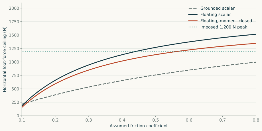
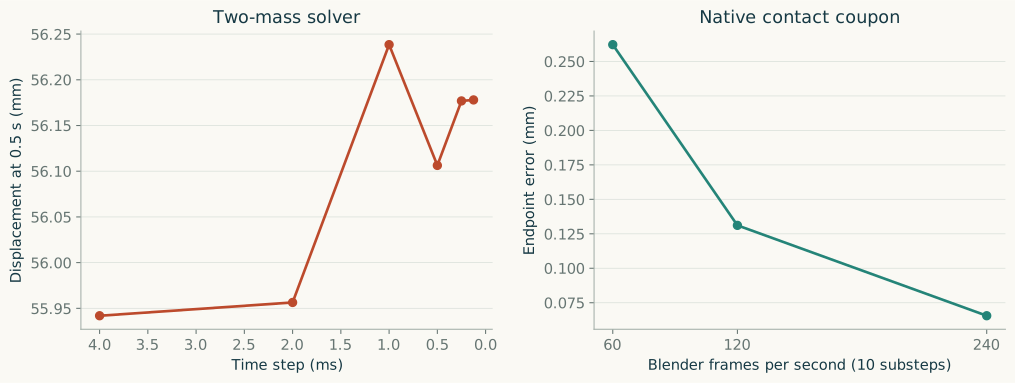
Illustration methods
The 45-second main film explains the two configurations, their assumed load paths, the prescribed drive-force pulse, and a fixed-seat case in which higher grip prevents slip. The optional contact-block film below serves a different purpose: checking the numerical contact solver.
The opening rowing figures are articulated Blender illustrations with prescribed component motion. The later seat-slip diagram and grip-comparison chart use numerical CSV trajectories. Body poses, proportions, oar motion, and sliding-rigger travel are prescribed. They do not establish joint forces or a dynamically realizable anatomical stroke.
The force comparison is labeled with its different hull conditions: constant-speed hull for the moving-seat rail and accelerating hull for the fixed-seat model. Force diagrams identify selected forces on the rower. Normal loading is prescribed; vertical and rotational dynamics are not solved by the pulse. The separate torque example above does not drive the animation.
“Seat-relative displacement” means sliding of the modeled pelvis relative to the seat. It is not elastic seat deflection, cushion compression, or tissue strain. The film slows physical time for explanation and holds selected results; the 120 mm event is a chosen cutoff.
Contributions and production. Jerry Decime supplied the research question and reported experience. The analysis, implementation, and figures were prepared with AI-assisted tools. Python calculations and Blender 5.2.1 LTS generate the model outputs and illustrations; local Kokoro speech synthesis supplies narration only. Rendering and narration do not add physical evidence.
Configuration comparison results · Film scales and data provenance · Watch the main film
Does the contact solver reproduce a known friction problem?
This optional demonstration checks a basic mechanical case in Blender’s rigid-body engine. Two identical blocks experience the same constant effective load on identical supports. Only friction differs. They do not represent the two rowing configurations.
Read the narration transcript
A separate software check
This separate software check uses two identical supports. Only friction changes. The blocks do not represent the two rowing configurations.
Known sliding solution
Block A has less grip and slides. Block B has more grip and holds. After eight tenths of a second, Block A has moved about a hundred and twenty-six millimeters.
What agreement establishes
Blender agrees with the analytical sliding solution to within a tenth of a millimeter. This verifies the contact calculation under the assumed loads. It does not validate a rowing power prediction.
Physical setup and expected motion
Blender 5.2.1 LTS, build 9e2066aef7ef, computes collision and friction for an active 85 kg box on a passive support. The reference box is 0.40 × 0.30 × 0.16 m. Its broad base prevents pitching at the selected load ratio.
The imposed effective gravity is gx = 157.272727/85 = 1.850267 m/s² and gz = −353.85/85 = −4.162941 m/s². This represents net external loading in a prescribed accelerating seat frame, rather than terrestrial gravity alone. The frame remains prescribed after sliding; it does not follow the changing hull acceleration of the coupled pulse model.
For the reference sliding case, the known solution from rest is:
x(t) = ½[gx − μ|gz|]t²
At t = 0.8 s and μ = 0.35, the analytical displacement is 125.836150 mm. The 240 fps run gives 125.901729 mm, a difference of 0.065579 mm (about 0.066 mm). The higher-friction block remains stuck. These are checks of implementation for an assumed friction law, not measurements of seat friction.
Restitution, linear damping, and angular damping are zero; deactivation is disabled. Both collision shapes are boxes with a 0.1 mm margin. The active bodies have no motion keyframes or hidden joints preventing slip. The engine exposes one contact coefficient here, unlike the separate static and kinetic coefficients in the pulse solvers. [5]
Cases, tolerances, and refinement
Eleven cases run at 60, 120, and 240 fps, each with ten substeps per frame and 100 solver iterations, for 0.8 s: 33 numerical runs, not 33 rowing trials. The finest substep is 1/2,400 s. Saved native scenes retain their physical setup and baked rigid-body caches.
| Cases | Expected behavior | Acceptance criterion |
|---|---|---|
| Reference slip; zero friction; calibration above threshold; product above threshold | Constant-acceleration sliding solution | Positive horizontal motion; endpoint error < 2 mm; rotation < 0.5° |
| Higher grip; zero tangent; calibration below threshold; product below threshold; moment inside | Sticking | |Δx| and |Δz| < 0.5 mm; rotation < 0.5° |
| Upward separation | Δz = ½(2 m/s²)t² = 0.64 m | Vertical endpoint error < 2 mm; |Δx| < 0.5 mm |
| Moment outside | Tipping despite adequate friction | Rotation > 5°; no analytical angular trajectory claimed |
| Across frame rates | Consistent contact mode | Each run passes; horizontal endpoint spread < 2 mm except for tipping |
All runs meet these criteria. Reference sliding endpoint errors are 0.262, 0.131, and 0.066 mm at 60, 120, and 240 fps. The largest analytical translation error is 1.333 mm in the coarse upward-separation case. This behavior is consistent with discrete engine integration; it is not a precision claim for real rowing contact.
Bullet’s default friction combiner multiplies the two material coefficients. With coefficients 0.35 and 1.0, calibration blocks stick at a horizontal/vertical load ratio of 0.34 and slide at 0.36. With both coefficients 0.35, they stick at 0.1125 and slide at 0.1325, bracketing the product 0.1225. These brackets check behavior around the predicted threshold, not an exact experimental transition. [6]
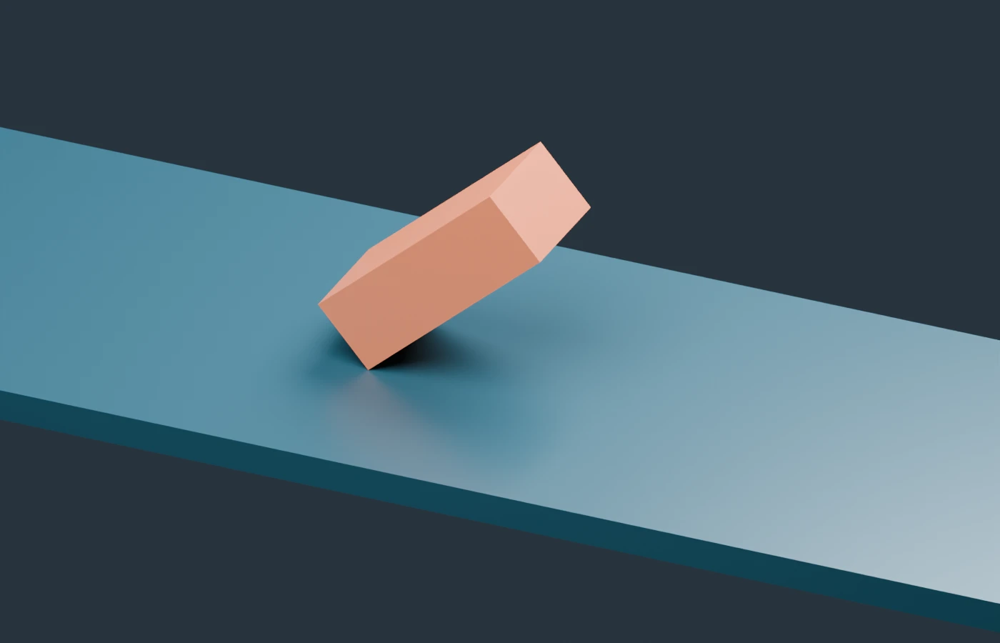
The rotational cases use a taller box, 0.20 × 0.30 × 0.60 m, with half-base b = 0.10 m and center height h = 0.30 m. Its required pressure center is s = hgx/|gz|. At load ratio 0.20, s = 0.06 m lies inside the base and it stays upright. At ratio 0.50, s = 0.15 m lies outside, and it tips despite μ = 0.90. Its 240 fps rotation is 48.78° at 0.8 s.
The block endpoint of approximately 126 mm and the pulse’s chosen 120 mm cutoff answer different questions. Their loads, friction laws, and frame conditions differ. They are not competing predictions of the same rowing motion.
All native results and tolerances · Native scenes and rowing illustrations
Power and related empirical evidence
A contact limit can rule out a prescribed motion without establishing an athlete’s loss of maximum power. Different body motion, force timing, or support conditions may allow other strokes. This study does not solve for those alternatives or evaluate matched power output.
The conditional mathematical argument is limited: restricting an available action set to contact-admissible actions cannot increase its maximum power. For a nonempty compact action set, continuous power objective, and nonempty closed admissible subset, the maximum decreases strictly only if every unconstrained maximizer is excluded. This statement does not determine whether that condition holds for either rowing configuration.
The source calculation’s 838.2 W example is 1,047.75 N × 0.8 m/s in a specified one-degree-of-freedom actuator proxy P = Fu. It is not measured rowing power, a physiological ceiling, or sustainable output. Neither 15.08 J of synthetic sliding loss nor the 157.27/14.54 N local traction ratio establishes a corresponding efficiency penalty.
Power transferred to equipment depends on each contact force and the equipment-side contact velocity in a declared frame; body energy changes are also needed for total athlete work. Oar forces and motion alone can omit relevant terms. No complete contact-power or physiological model is implemented here. [3]
Published experiments provide context for why seat support matters. Eleven trained female rowers produced approximately 12% more mean mechanical power during five-stroke ergometer starts when strapped to their sliding seats. A later study of nine trained male single-scull rowers reported an approximately 0.45 s advantage over 75 m starts. These interventions addressed restraint and potential contact loss on sliding seats; they did not compare fixed-seat sliding-rigger boats with moving-seat boats or measure the present horizontal-slip mechanism. [1] [2]
Whole-boat efficiency also involves hydrodynamics. Under the assumed drag law D = kV² for V ≥ 0, mean drag power is k⟨V³⟩. The third moment depends on both variance and skewness, so reducing speed variance alone does not guarantee lower mean drag power if the distribution otherwise changes. Related rowing studies examine velocity fluctuations and drag; they do not calibrate this model’s coefficient. Kinetic energy transferred to moving bodies is not automatically an irreversible loss. [7] [8]
Limits of the evidence
Computational verification. Analytical solutions, numerical refinement, and a second contact implementation check the specified mechanical calculations. No instrumented rowing trial is included. Agreement with Blender does not establish a real power penalty.
Equipment and body motion. Applied forces, friction, masses, and geometry are illustrative. The pulse models suppress vertical and angular motion and treat the rower as a translating mass. Rigger inertia, oar–water loading, muscles, and a full recovery phase are not solved.
Comparison boundary. The local moving-seat rail uses a constant-speed hull; the fixed-seat model has a freely accelerating hull. They illustrate differing support mechanisms under imposed loads, not a matched whole-boat experiment.
Contact and tissue. Sliding, separation, and tipping are distinct rigid-contact limits. Cushion compression, elastic seat deformation, tissue shear, discomfort, and injury are outside the tested models. Skin and dressing research does not supply rowing-seat coefficients or individual tolerance thresholds. [9]
Uncertainty. Refinement characterizes discretization behavior. Uncertainty in real forces, friction, geometry, and body motion has not been quantified. Detailed digits allow reproduction of the calculations; they are not measurement accuracy.
Scope of the conclusion. The models show how insufficient seat support can exclude a prescribed drive. They do not establish how frequently this occurs, a universal configuration ranking, or a difference in maximum power, speed, or metabolic efficiency.
Research data and models
The archived calculations make the illustrative results traceable to their equations and inputs. Data are simulation outputs, not measurements of a rower or boat.
| Research material | Contents and purpose |
|---|---|
| Models and research data | Fixed-seat and moving-seat Python solvers, pulse trajectories, parameter sweep, verification reports, and a research guide |
| Configuration comparison | Snapshot seat loads, moving-seat travel, fixed-seat slip, and ten comparison checks |
| Blender models | Eleven contact cases, paired solver-verification scene, and prescribed rowing illustrations |
| Native contact results | All 33 runs at three frame rates, analytical predictions, tolerances, and refinement checks |
| Illustration provenance | Film timing, force and displacement scales, and source-data identifiers |
The computations used standard-library Python for reduced dynamics, SymPy 1.14.0 for symbolic checks, and Blender 5.2.1 LTS for native contact cases. The archive includes source files and checksums so reported results can be inspected and reproduced.
References
The sources below provide empirical rowing evidence, contact-mechanics background, software documentation, and the historical context for the two boat configurations. The model parameters are illustrative rather than fitted to these studies. References accessed 13 October 2026.
- Van Soest & Hofmijster (2009). Strapping rowers to their sliding seat improves performance during the start of ergometer rowing. Journal of Sports Sciences 27:283–289. University publication record and abstract. DOI: 10.1080/02640410802495336. Reports an approximately 12% increase in mean mechanical power during five-stroke ergometer starts in 11 trained female rowers.
- Van Soest, de Koning & Hofmijster (2016). Strapping rowers to their sliding seat improves performance during the start of single-scull rowing. Journal of Sports Sciences 34:1643–1649. University repository paper. DOI: 10.1080/02640414.2015.1130235. Reports an approximately 0.45 s advantage during 75 m starts in nine trained male single-scull rowers. The intervention addressed seat restraint and contact loss.
- Hofmijster et al. (2018). Mechanical power output in rowing should not be determined from oar forces and oar motion alone. Journal of Sports Sciences 36:2147–2153. University publication record and abstract. DOI: 10.1080/02640414.2018.1439346. Supports the need for complete power accounting.
- Tedrake, Underactuated Robotics. Planning and Control through Contact and Highly-articulated Legged Robots. MIT course text. Background for unilateral contact, friction cones, and center-of-pressure constraints.
- Blender Foundation. RigidBodyWorld Python API. Documentation for frame substeps and solver iterations. Simulation version: 5.2.1 LTS; the current documentation may describe a newer release.
- Bullet Physics source code. btManifoldResult.cpp, calculateCombinedFriction. Default material friction is a product, subject to a clamp. The current source is explanatory; the installed build was checked with separate calibration cases.
- Hill & Fahrig (2009). The impact of fluctuations in boat velocity during the rowing cycle on race time. Scandinavian Journal of Medicine & Science in Sports 19:585–594. Publisher abstract. Related primary research; not a source for a specific sliding-rigger time advantage in this evaluation.
- Greidanus, Delfos & Westerweel (2016). Drag and power-loss in rowing due to velocity fluctuations. Procedia Engineering 147:317–323. TU Delft repository. DOI: 10.1016/j.proeng.2016.06.299. Related experimental flow research, not calibration for this reduced model.
- Polliack & Scheinberg (2006). A new technology for reducing shear and friction forces on the skin: implications for blister care in the wilderness setting. Wilderness & Environmental Medicine 17:109–119. Publisher record. Background on skin/dressing interfaces; no coefficients or medical predictions are transferred to rowing.
- World Rowing (2022). Scull and Sweep – Defining Rowing Series Part 3. Governing-body explanation of sculling as rowing with two oars per rower.
- The Boat Race Company. The Men’s Boat Race Results, 1873 entry and note 14. Records the first use of sliding seats in this event; this is not a claim that the seat was invented in 1873.
- Michael F. Davis (1878). Improvement in outrigger-boats, US Patent 209,960, issued 19 November 1878. Describes a stationary seat combined with moving foot support and outriggers, and explains the aim of retaining leg contribution while moving a lighter assembly. Historical design evidence, not validation of the present model.
- Ozawa Rowing (1982 experiment; account updated 1998). Sliding Rigger in 1982: experimental works. A builder’s account of converting a wooden single scull to fixed-seat, sliding-rigger operation. Describes reduced movement of the rower’s mass and reduced pitching and surging as design motivations; no claimed speed gain is used as evidence for this study.
The supporting studies concern their stated equipment, tasks, and populations. Their results do not establish a fixed-seat sliding-rigger power penalty or calibrate the illustrative coefficients used here.